Analyzing the design and energy efficiency of compressed air systems through simulation
The ultimate way to shorten your design phase

For years, simulation-based analyses of air suspension systems have been carried out in the field of heavy machines, commercial vehicles, and buses and used for system design and energy analysis. Most of these systems are passive level-controlled systems that increase the ride comfort and functionality of the vehicles. A great example is a bus in urban traffic, which can lower the chassis on one side at bus stops to make it easier for passengers to get on and off the bus or make their stay more pleasant during the journey (thanks to the high-ride comfort of the air suspension). This also applies to trucks in long and short-haul operations and to operating heavy machines to create the most comfortable experience possible for the user.
In addition to the existing requirements for automotive safety and comfort, requirements will become even more stringent with the switch to autonomous driving for passenger cars. To optimize autonomous drive time for other activities, such as working or reading, while undisturbed and without physical discomfort (e.g., motion sickness), it is necessary to reduce the vehicle chassis accelerations in relation to external influences, like road bumps, or perceived accelerations as a result of starting and braking processes or cornering. This can only be achieved by an active suspension system.
In current luxury-class model vehicles and EVs, air suspension systems have been standard for some time and can be used in an active version to influence the isolation behavior:
- High comfort due to soft basic tuning
- Load changes are compensated by a level control system
- Additional comfort functions such as lowering the vehicle’s body for entry or raising it for off-road driving and light trucks
These advantages of air spring systems are used as an initial point for further developments. With appropriate enhancements such as adapted components, additional valves, and adapted control strategies, ride comfort and safety can be increased. Which adaptations and extensions lead to the desired behavior can be determined by simulation.
However, these benefits come at a price: increased energy requirements and components and correspondingly increased weight.
Mitigating the risks and challenges of air spring systems with simulation software
Numerical system simulation has become an essential component in the design and analysis of both system components and the overall system (chassis, air suspension system, vehicle body). In addition to the functional analyses of a ride’s safety and comfort, analyses of energy consumption and noise behavior also play a significant role, particularly in the case of electrically powered vehicles, trucks, and buses.
Analyzing a complete vehicle using SimulationX: suspension behavior
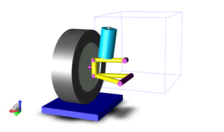
Now we will dig deeper into a specific example of how simulation, specifically SimulationX, can help you. Let’s consider suspension behavior; there is a trade-off between safety and comfort. In the analysis of the vertical-dynamic spring-damper system, quarter-vehicle models (Fig. 1) are used, among others. In this quarter vehicle model, the chassis and the tire are represented by a point mass model, connected by a spring-damper system. The vertical accelerations of the chassis are analyzed for different excitations of the driving surface which are introduced at the wheel. These can be simple signal-based excitations, such as sinusoidal oscillations, as well as imported curves from test drives with real vehicles.

Fig 1: Diagram and 3D view of a quarter vehicle model in SimulationX
An analysis of the complete vehicle is made possible by coupling the air suspension system with an MBS chassis model. The animation to the left shows that tire models within SimulationX can be used for the chassis, which, in conjunction with models for uneven surfaces, transfer corresponding excitations to the vehicle. Further excitations result from the vehicle dynamics, e.g., during cornering. As a result, the accelerations of the chassis can be analyzed in the existing six degrees of freedom. An example of this is the multibody animation model of a truck on an uneven road shown in the animation on the left.
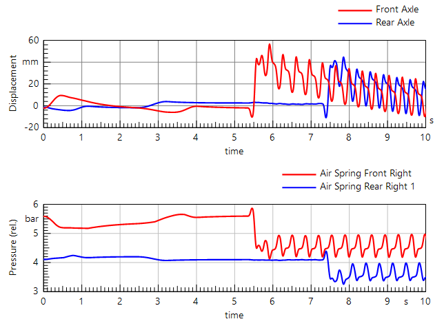
The diagram in Fig 2 shows the transient characteristics of the air spring travel and the pressure in the air spring chambers. In the range from 0s to 5s, the response to the drive-off and the acceleration of the vehicle on even ground can be seen. You can see the reaction to driving over the hump track in the further course.
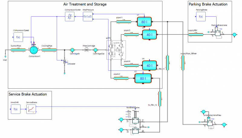
In addition to the analysis of the driving behavior, analyses of the compressed air system are also necessary. The provision of energy in the form of compressed air must be guaranteed in every driving situation and possible system failures must be included. In the simulation of the pneumatic system, it is possible to calculate times for reaching driving readiness, in particular the filling of the compressed air tank and the influence of external influences such as temperature and compressed air changes for a wide range of climatic zones. A simplified model of a compressed air supply is shown in Fig. 3. Depending on the analysis objective, the model's level of detail can be adapted.

Fig 2: Simulation Results of Air Spring Displacements and Air Spring Pressures at Front and Rear Axle

Fig 3: Compressed Air System Commercial Vehicle – generation, air treatment, distribution, and storage of compressed air
Understanding the complete system behavior, simply and early, on a Virtual Proving Ground
In all the analyses, the evaluation of the overall system behavior is important, and SimulationX supports the calculation engineer with a range of analysis options and ready-made models and components. On one hand, these are dynamic calculations of the system in the time domain as well as in the frequency domain. On the other hand, the libraries for 1D/3D mechanics, pneumatics, and hydraulics are available for model creation as well as signal elements for mapping controller structures. What SimulationX users all over the world value the most is the fact that accurate simulation results are available from day one: This leads to significantly fewer physical tests. In addition, system simulation extends the possibilities for analyzing alternative concepts as well as evaluating physical quantities which are difficult or impossible to measure in the real system.
To wrap up this topic, let’s zoom out to connect system simulation to an even bigger story. Few would dispute that the reliance on physical tests and prototypes has already dramatically decreased because it is simply no longer sustainable – neither financially, considering the significant amount of time and cost for hardware tests, nor with regards to the enormous waste of emissions and raw materials. Which bus, truck, or automaker can continue tolerating long delays or, ultimately, a full-stop for market launch due to queues in front of busy or even closed test facilities? Which OEM can afford the massive cost of a second test run because the first one didn’t bring the desired certification? Instead, can you picture a world where engineers work on virtual prototypes remotely, having the opportunity to make agile adjustments towards ultimate performance and digital pre-certification because they can trust the simulation results that they achieve?
ESI has been invested in working to make this vision a reality. We are revolutionizing ways to connect simulation tools to build a virtual proving ground – the virtual counterpart of the windy, dusty, muddy proving ground on which engineering teams test physical prototypes for their heavy machinery and equipment. It allows performance engineers to virtually assess the full picture of their final vehicle in real life: from designing safer, cleaner products to achieving product pre-certification despite constantly evolving regulations and even meeting regulations and targets for interior and exterior noise & acoustics.
By the time they enter the physical proving ground, engineers completely understand the performance of their new product in terms of safety, productivity, and sustainability before market launch and throughout its lifecycle. In a nutshell, by the time they enter the physical proving ground, OEMs have all the confidence they need to acquire certification for new technologies introduced right the first time. And this is only the beginning of the new ‘virtual’ test reality…
Learn from the system simulation experts
In general, the benefits of the virtual proving ground and simulation will automatically keep you one step ahead. Don’t wait until your products are physically ready to improve their performance – start your transformation today!
For more information on how SimulationX can help you, watch the On-Demand webinar I hosted related to the content in this blog.
Do you find yourself asking questions like, “What is the best setup for the desired electric vehicle characteristics under different driving and environmental conditions? Or “How do the controls of driving performance and comfort influence the range?” If so, watch this webinar titled “Assessing the Range of an Electric Vehicle under Diverse Conditions” where my colleague Salim Chaker will address these questions and more!
Carsten Obenaus is currently working as an Application Engineer with a specialty in Customer Experience for Systems Simulation at ESI Germany. He joined ESI in April 2005 and has been acting as a project and development engineer for ESI’s Systems Modeling solutions across various industry applications. His areas of expertise include modeling hydraulic and pneumatic systems, vehicle dynamics (braking, chassis, suspension, steering), and thermal systems modeling. He has a diploma degree in Automation Engineering from the University of Applied Sciences Dresden, Germany. His scope of work includes application and engineering services, consultancy, training, and customer support for modeling and simulation of fluid power systems as well as software development of SimulationX fluid power libraries such as hydraulics, pneumatics, and customer-specific libraries.