PAM-STAMP
Hot forming is growing rapidly, and is a fascinating manufacturing technique, where the good formability of the warm blank is combined with exceptional strength of the end part due to the quenching in the tools. No traditional available material that is formable is even close to the strength of the hot formed steel. This makes it a natural choice for the crash relevant parts in the car. Today all major OEMs work with hot formed parts in the cars as crash re-enforcements. It allows building even small sized cars with an outstanding crash performance – enabling the traditionally weaker group A cars also to get the 5 stars in the EURO-NCAP crash tests (e.g. Fiat 500).
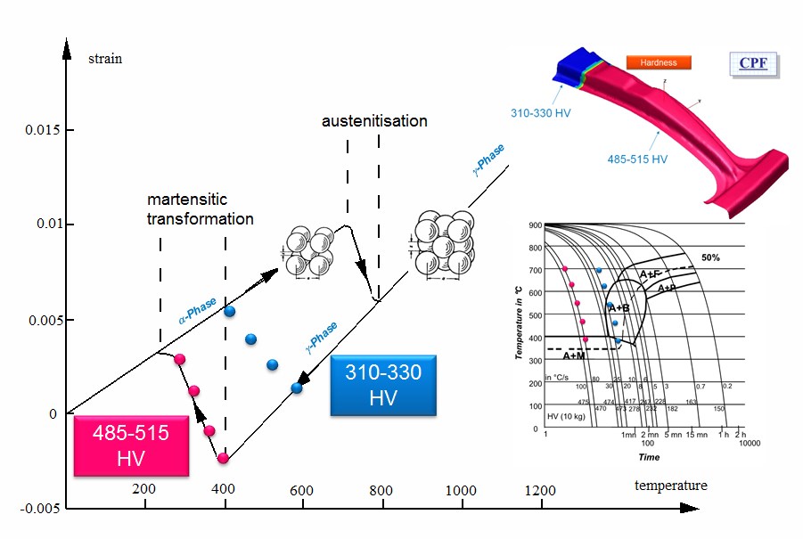
The hot forming process and involved physics
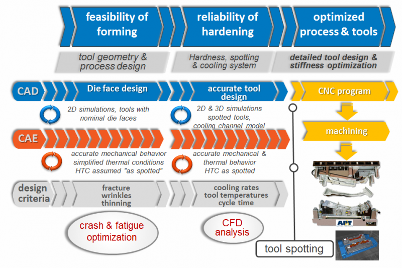
This means that looking only on the formability of the part during stamping doesn’t really make sense. The whole chain has to be kept in mind – this from early design stage on. To get the properties of the end part right is crucial to achieve the crash performance. This means that the crash engineers have to rely on the stamping department to manufacture the parts with the right properties.
Hot forming itself is a manufacturing technique where different fields will play together to make it work or not. The stamping department has to build knowledge now also in metallurgy, heat transfer, cooling and fluid dynamics – areas where normally several specialists are involved.
So to summarize, with this new process, the stamp engineer is suddenly confronted with several new areas where he has to have a high level of knowledge to get the process right.
Even for the most talented engineers, it will be to ask for too much to become an expert in all these fields. This is typical area where the virtual manufacturing can play an important role in getting the new processes running. The part manufacturing with all its different aspects can be tested virtually before the expensive hot forming process is started. Also the part performance in the final crash can be tested virtually. This is again a step towards the end to end virtual manufacturing – even if the challenge to simulate all the different aspects still remains.
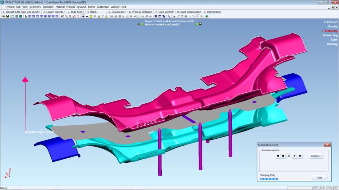
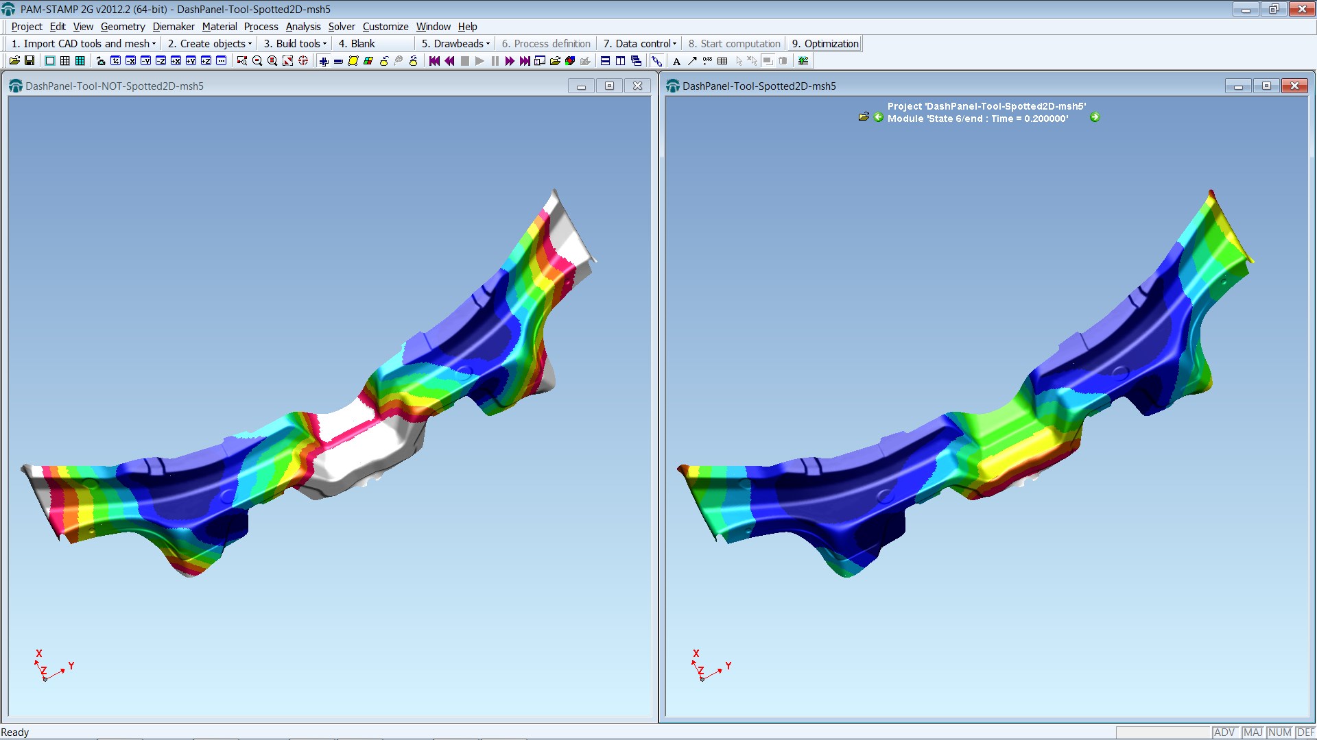
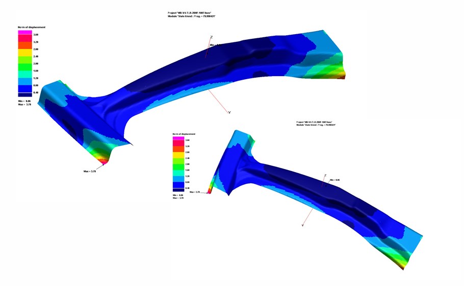
The complete value chain is nowadays available, allowing analyzing the complete press hardening process from initial part cost to distortion after quenching, cooling channel analysis and virtual reality check.
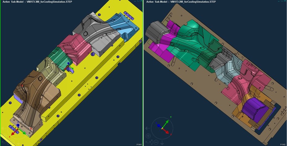
Hot Forming – Cooling Capability of the Die
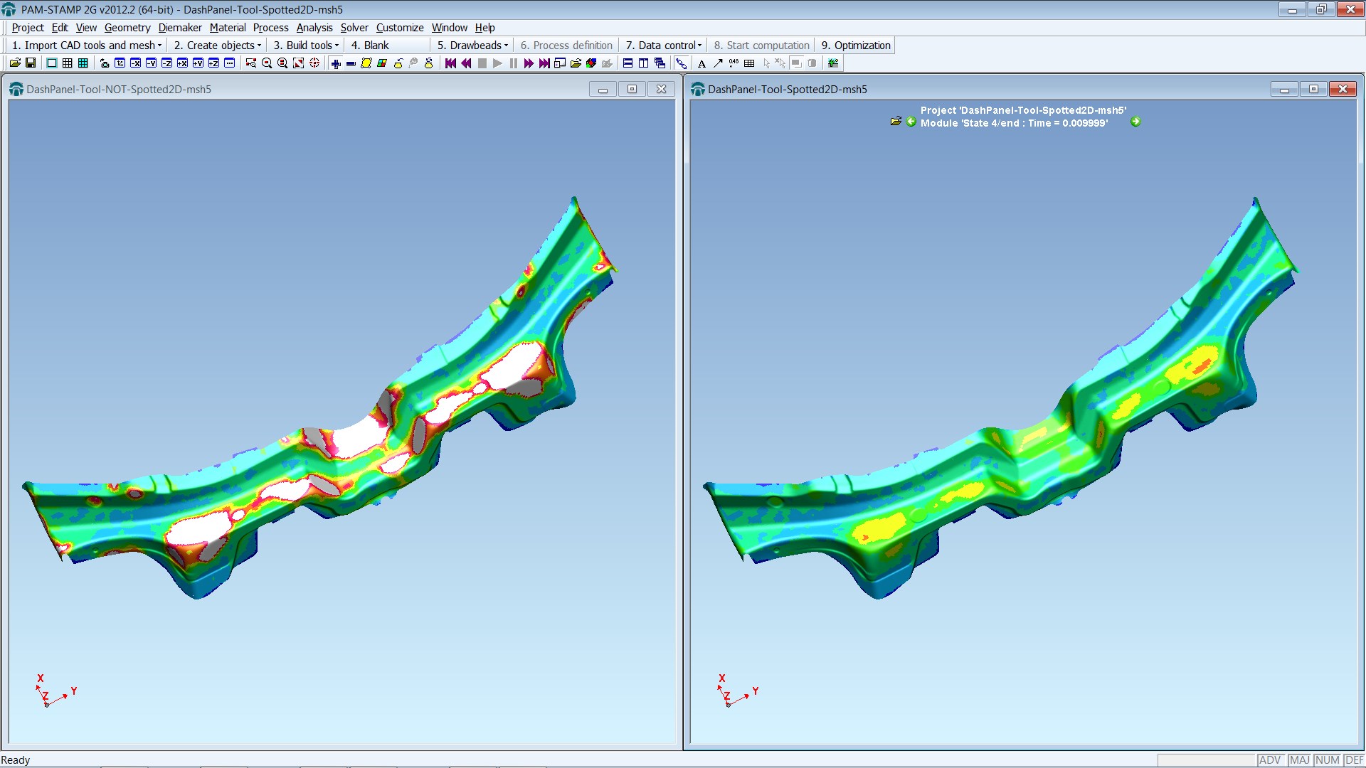
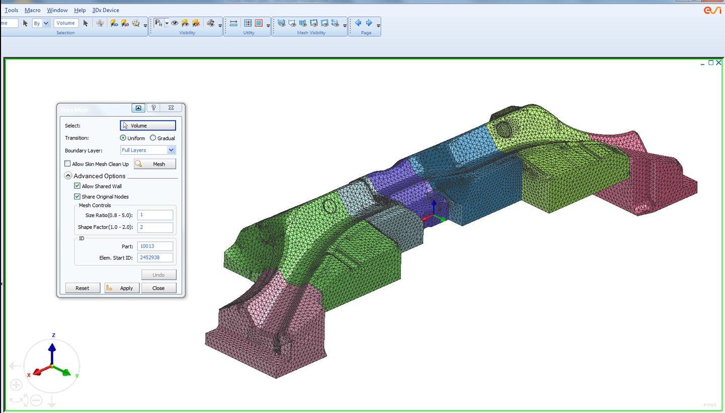
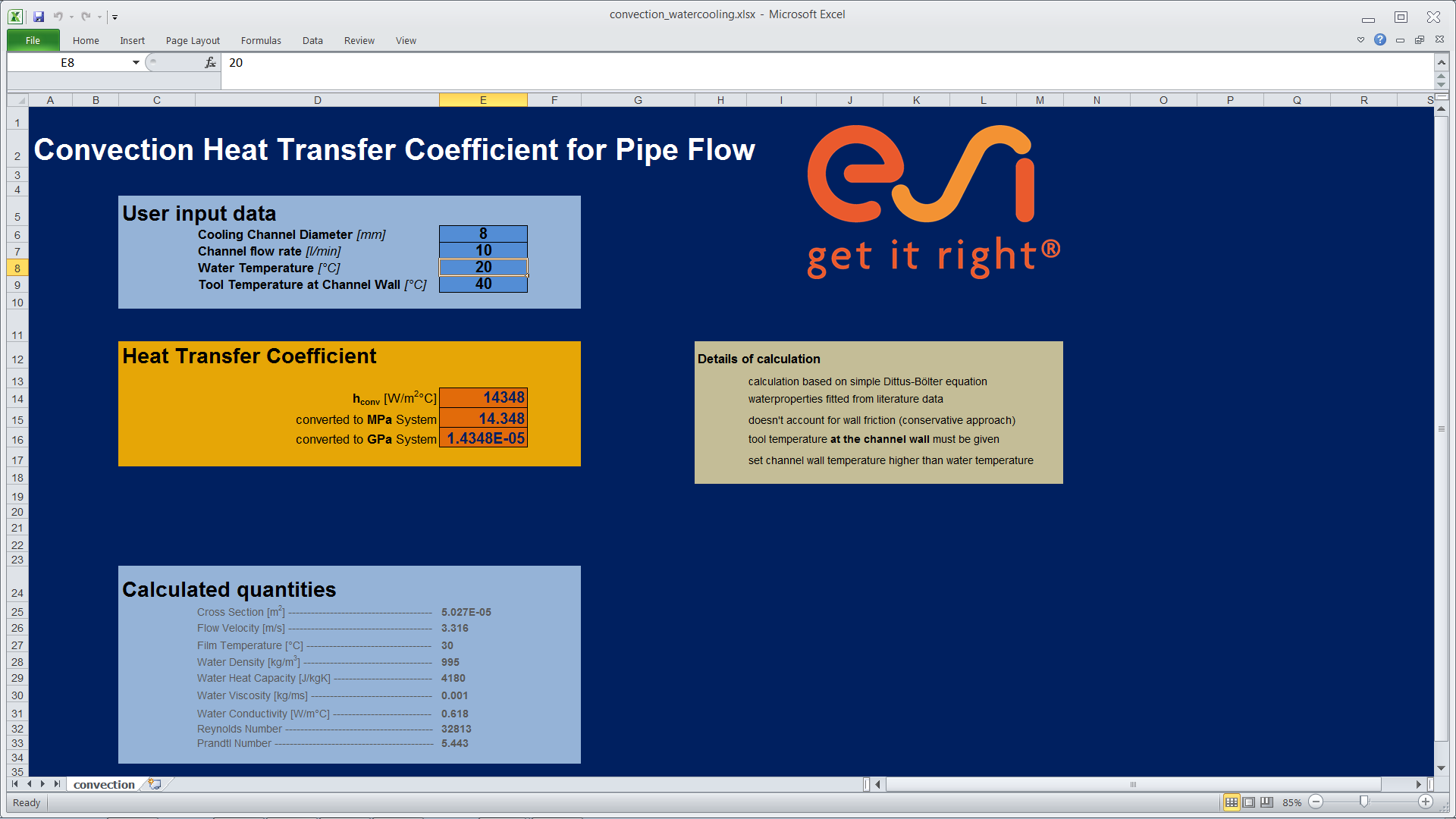
The cooling channel analysis is done with a heat transfer model – taking into account realistic blank temperatures from the forming simulation. Heat transfer maps are coming from the CFD analysis, see next chapter. A dedicated tool is available to assemble the CAD and mesh the complex 3D die in no time.
